DEXTERRA
SUMMARY
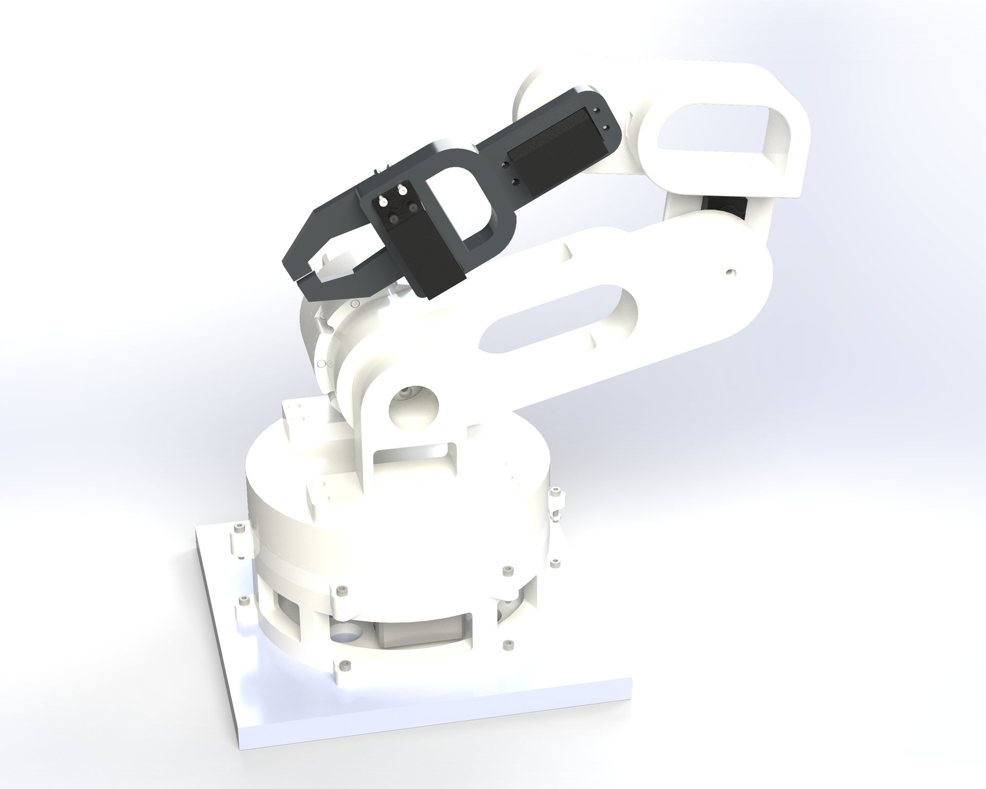
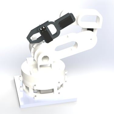
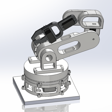
Dexterra is a 4-DOF , user controlled robot arm capable of lifting several different objects. It is lightweight, highly precise, and strong. The design consists of 3D printed parts, making it an affordable, yet reliable take on the robot arm.
Degrees of Freedom: 4
Max Payload: 454 g
Weight : 1.34 kg
Strength-to-Weight Ratio: 1:3
Max Reach: 430 mm
Cost: $202.80 (Max budget: $300)
Specs:
Background
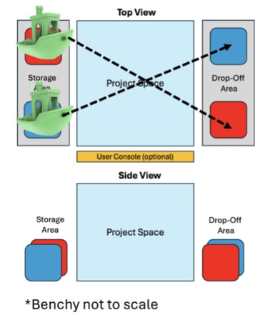
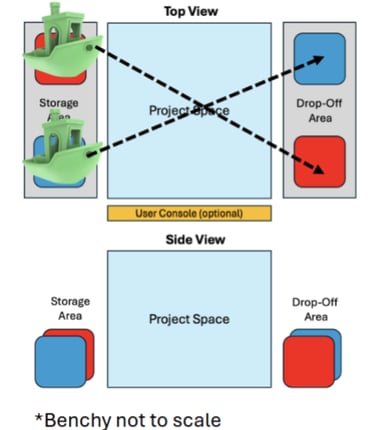
As part of our ME380 course, we had to work in groups of 5 to design a device capable of moving objects from a defined storage area to a defined drop-off area. Ontop top of this, we had to pick two additional criteria to hit with our design. The criteria we set were as follows:
The device must have a 1:3 strength to weight ratio
The device must be precise, with repeatable positioning accuracy of less than 3 mm in the planar (x–y) direction.
DESIGN BREAKDOWN - MY CONTRIBUTIONS
During this project, I took on several responsibilities, ranging from technical design to project management. My contributions are summarized below:
Arm modelling: performed calculations to estimate the torque expected at each joint under a worst case loading scenario.
Base Joint: designed the rotational base joint, implementing a compact gear train for optimal performance.
Shoulder joint: designed a dual stage planetary gearbox capable of producing approximately 4.2 Nm of torque to drive the shoulder joint.
Manufacturing: 3D printed and assembled several components and drafted an engineering drawing.
Project management: coordinated group members and oversaw B.O.M development.
Static Calculations - Modelling the Arm
The goal behind my calculations was to determine the torque required for each joint, with the goal of ensuring that the design specification of a 1:3 strength - to - weight ratio was met. We used these calculations to spec our motors and gear trains. These calculations relied on simplified but conservative models:
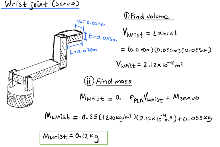
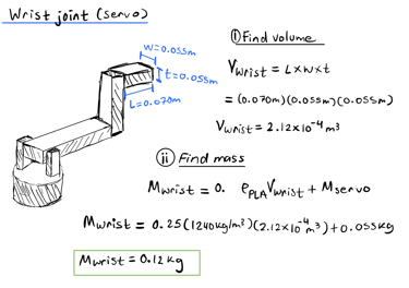
Firstly, I estimated the final mass of the robot by multiplying the expected density of each component by the predicted volume. To do this:
1. The geometry of the robot arm was broken down into simplified shapes
Rough dimensions desired for the final build were used to model these shapes, allowing the volume of each component to be estimated.
2. These values were then multiplied by the average density of PLA and PETG.
3. A 3D print infill between 15%-20% was assumed for each of the components.
For simplicity, wall and shell layers were not calculated but accounted for with a 0.25 factor to make the calculations more conservative.
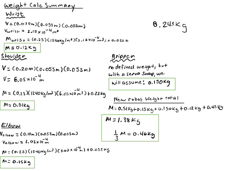
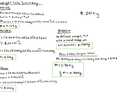
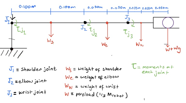
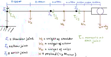
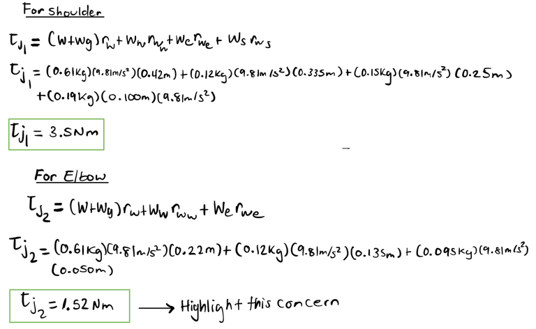
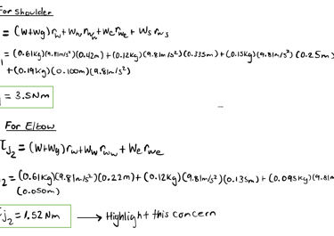
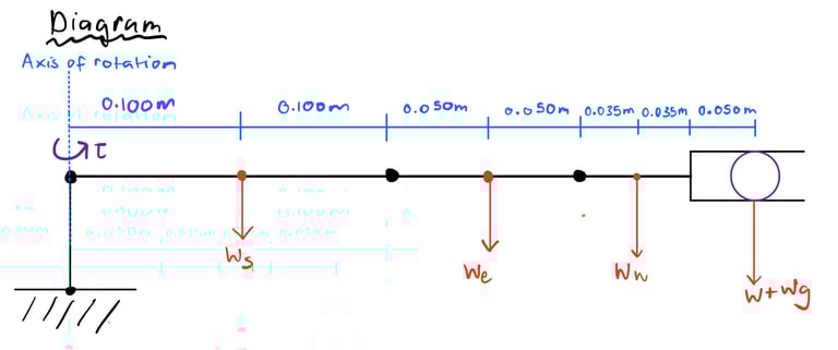
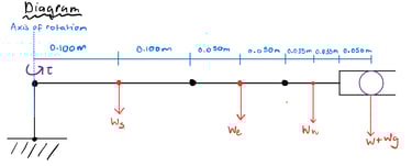
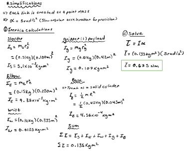
After estimating the total mass of the links, I calculated the worst-case scenario torque required to lift 1/3 of the robot’s weight (0.46kg). I used a simplified diagram of the arm in its least advantageous position to find the moment created at each joint by the weight of each link and the weight of the 0.46kg payload:
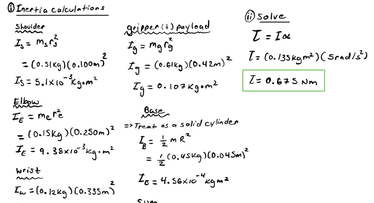
I used a slightly different approach for the rotational base joint. The main concern with this joint came from the inertia it would have to overcome to rotate the weight of the entire arm. To calculate the torque required to do this:
All links were treated as point masses and the inertia of each was calculated using parallel axis theorem
Inertia of all links + base were summed, to estimate the total inertia about the base joint
Angular accelerations that the arm could potentially be ran through were used to estimate the torque that may be required at the base
Base Joint Design
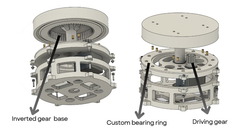
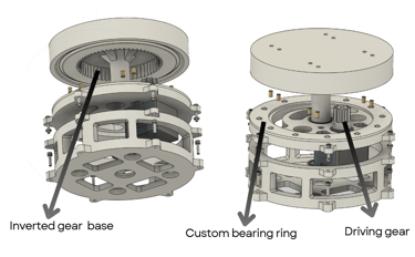
I designed the base joint for the robot arm.:
Implemented a 6:1 reduction to ensure the robot could generate enough torque to rotate smoothly on its base under high loads and angular accelerations
Consists of a driving gear that interacts with an inverted gear built into the base. A custom designed ball bearing ring acts to reduce friction between plastic components, increasing efficiency and precision.
Implemented several slots for passive cooling of the driving motor and weight reduction.
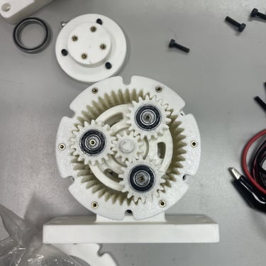
Shoulder Joint Design - Dual-Stage Planetary Actuator
Of all the actuators I've designed thus far, this is likely the one I am most proud of due to how compact it is and how quickly I had to design it. To meet our worst-case torque requirement for the shoulder joint, we needed an additional gear reduction ontop of our motor:
I originally went with a 15:1 dual-stage cycloidal drive design for compactness and low backlash. This prototype failed miserably however. It was prone to extremely high levels of backlash and failed to meet torque requirements due to efficieny losses.
After some root cause analysis, this was explained by high levels of friction between interacting components, in addition to skewing of the ring pins used to transmit loads to the output hub. These issues arose due to my attempts to make the design as compact as possible, leading to poor tolerancing, poor press fits, and low friction mitigation.
In general, the design was also a pain the butt to assemble, and was NOT a great design from a DFMA prespective at all.


My depressing initial cycloidal drive attempt
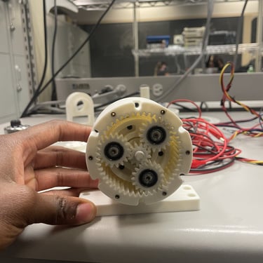
At this point, school began to get really hectic. To save on time, instead of trying to re-iterate on this design, I opted to try out a dual stage planetary design instead. Keeping in mind my old failures, I went on a coffe-fueled CAD spree over the corresponding weekend and created a new actuator design over the course of those 48 hrs. The second iteration summary is as follows:
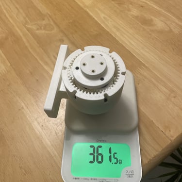
25:1 dual -stage planetary gearbox, over-speced ratio for added F.O.S and to account for efficiency losses.
Peak holding torque of 4.2 Nm providing a F.O.S of 1.2 (needed 3.5 Nm for shoulder according to calcs) , while weighing only 361.5 g
Total cost to manufacture: $15.49
In general, to achieve this I did a lot differently during this design sprint:
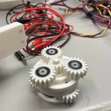
Firstly and most obviously, I picked an easier to design reduction system. Planetary gearsets are often simpler to deal with than cycloidal gear trains. In this case, a planetary style approach was good enough for what I needed.
Secondly, I put an emphasis on friction reduction through optimization of gear backlash to prevent binding, the utilization of bearings wherever applicable, by minimizing plastic on plastic contact in transmission locations wherever possible, and by utilizing lubricant.
Thridly, I put an emphasis on minimizing skewing and wobble through several locating features for each mating stage.
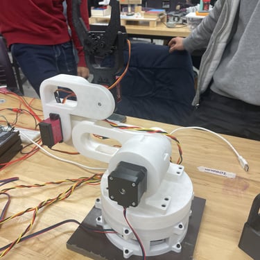
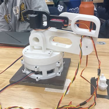
Manufacturing and Project Management

Actuator robot curls

Initial Test
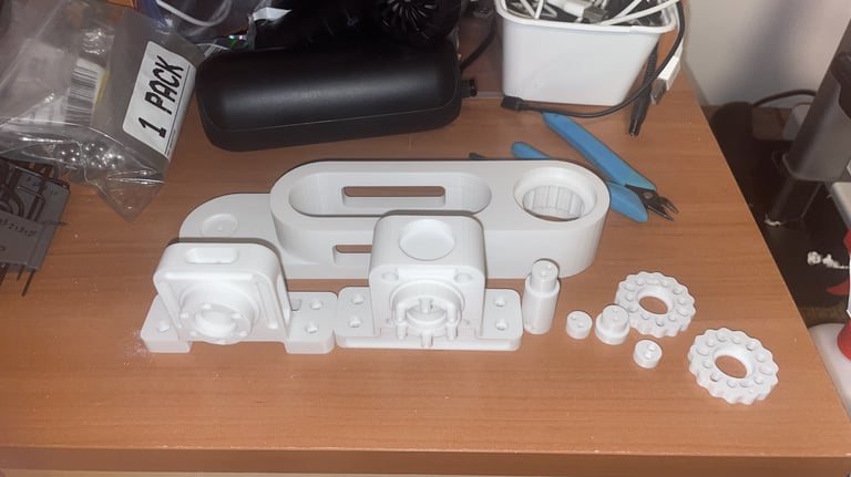
I played a large role in maunfacturing and assembling the robot:
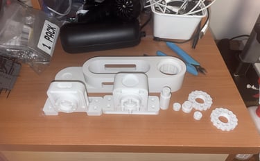
3D printed several of the key subsytems, optimizing print profiles for rigidity and weight minimization
Drafted an engineering drawing for the base plate to which the robot was attached for manufacturing
Assembled several of the subsystems (shoulder joint, base joint, elbow joint) by hand
On the project management side I oversaw several key operations during the project:
Oversaw B.O.M management and sourced several of the components and materials used
Developed a schedule and Gantt chart for project completion
Played a pivotal role in documenting project progress and engineering decisions
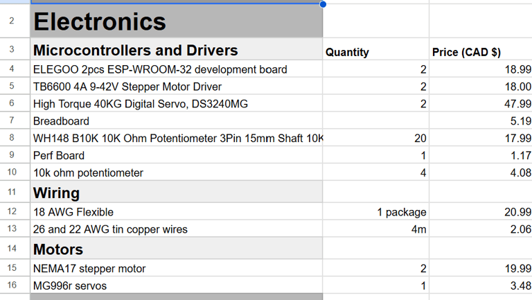
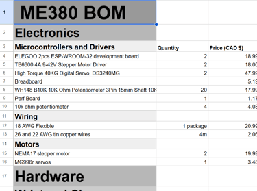
BOM Snapshot
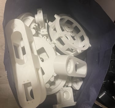
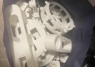
Scrapped Prototype Prints (we iterated a lot)


