THE DREAMMAKER
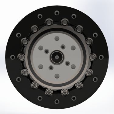
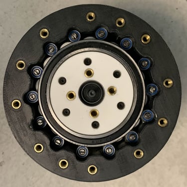
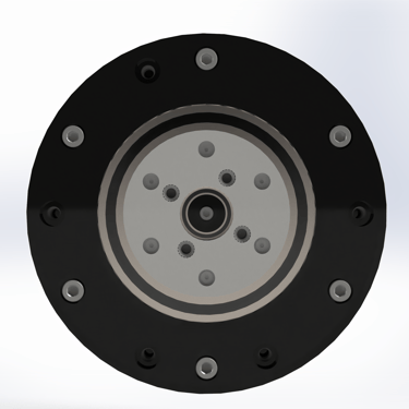
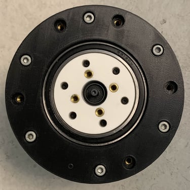
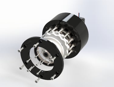
The DREAMMAKER is a 3D printed cycloidal actuator with a 13:1 reduction ratio designed for robotic applications. It was designed to be a cheap, efficient, reliable means of actuation from robotic arms and humanoid robotic joints. The project stemmed for my growing interest in the field of robotics, and a budding desire to experiment with different reducers with the hope of eventually developing my own robotic arm or prosthetic.
Design Highlights:
Boasts exceptional stability, with minimal vibration and wobble
The design is easily backbrivable
Boasts 52% torque output efficiency, a great rating for 3D printed reducers
The reducer is very light, weighing approx 3.2 lbs
This project required lots of research, as I did not just want to make a functional reducer, but I wanted to make the most optimal one I could, with the goal of maximizing performance and efficiency.
I did complex force analysis to spec out bearings for the build and to ensure failure didn't occur at critical components. I made a development log that details all the preliminary research and calculations done for the project. This log is attached further below on this page. It is written in a formal report style to make it easy to read for people who may want to use it as a guide for their own designs.
SUMMARY
DESIGN BREAKDOWN
13:1 Reduction Ratio enabled by 14 ring gear pins with free rolling bearings to reduce friction
Dual cycloidal discs 180 degrees out of phase to reduce vibration
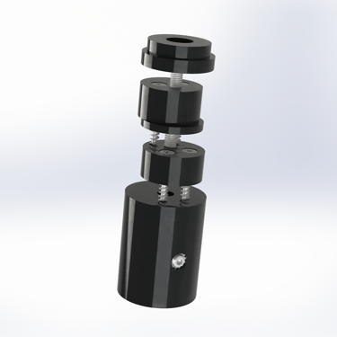
4 piece output shaft connected by self tapping screws and one final M3 bolt
Bearings on each disc and eccentric shaft component for further reduced friction
An output shaft with six output pins for a balance of efficient transmission and structural integrity
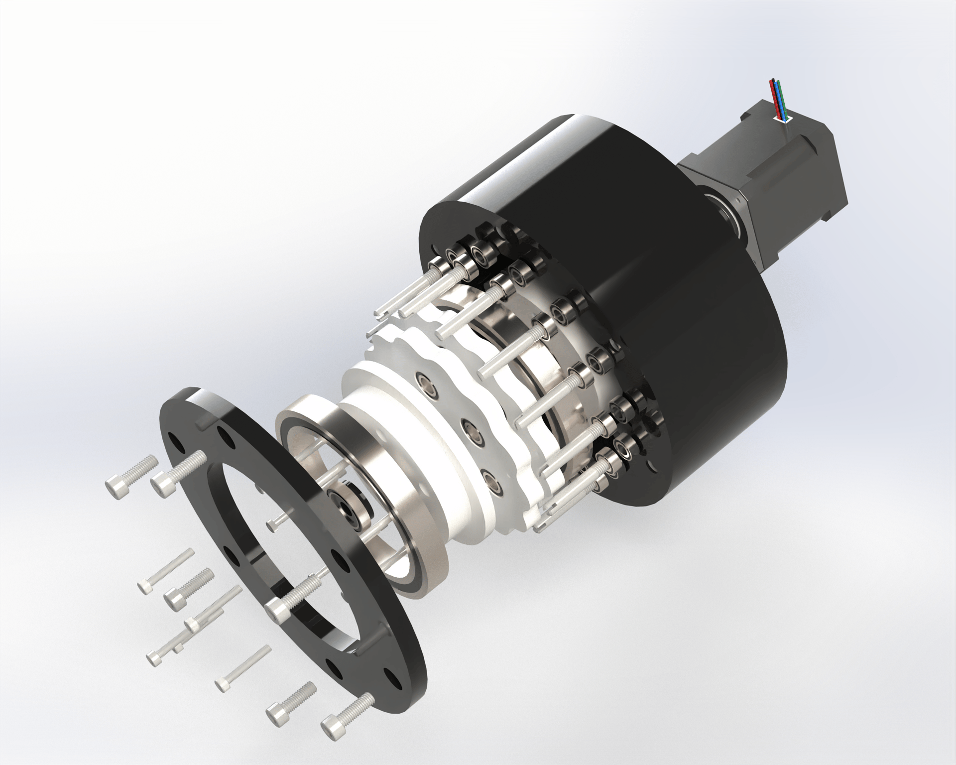
Like any cycloidal reducer, the DREAMMAKER consists of 5 main components:
High Speed Input Shaft:
The high speed input shaft is where the motor driving the reducer is attached. In most cases this is usually a high speed, low torque motor, but can differ depending on the design.
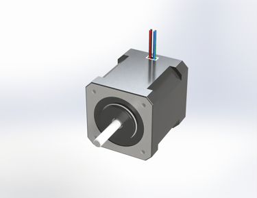
In this case, a conventional Nema 17 stepper motor was used and is mounted directly to the ring gear housing.
Eccentric Shaft:
The eccentric shaft is attached to the high-speed input shaft. The high speed input shaft drives this eccentric shaft which contributes to the oscillating motion of the cycloidal discs.
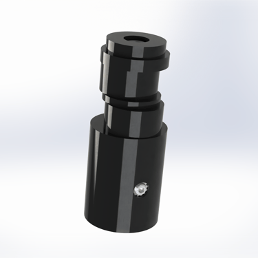
The DREAMMAKER's eccentric shaft is split into 4 stages and each stage is connected to one another by self-tapping screws.
An M3 bolt is inserted through a hole in the final stage and goes through the entire shaft for greater strength. The first stage is coupled to the motor with an M3 set screw.
Cycloidal discs:
These interact with the ring pins in the ring gear housing to help create the oscillating motion and gear reduction seen in the reducer.
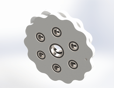
The DREAMMAKER utilizes two cycloidal discs offset by 180 degrees to minimize vibrations and wobble. There are tiny holes in each disc that can be aligned to ensure proper offsetting during assembly.
Additionally, the discs possess holes for the insertion of the eccentric bearings and bearings for the output pins to interact with for smooth contact and reduced friction.
Ring Gear Housing:
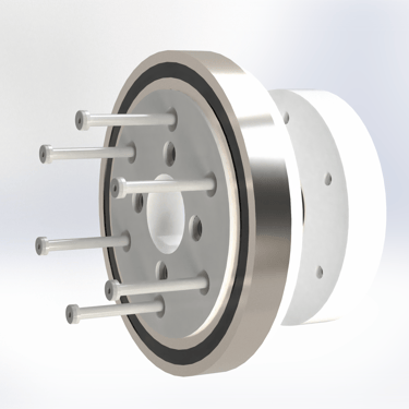
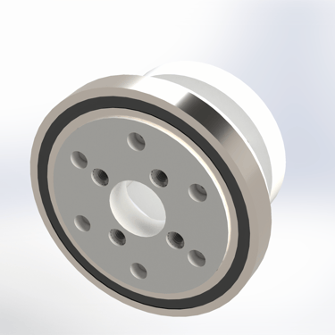
This houses all the components of the reducer, and contains the ring gear pins in which the cycloidal discs interact with.
The DREAMMAKER possess fixed ring pins with bearings for smooth rolling contact and reduced friction. Threaded on one end studs were used as the ring pins to ensure they were held securely in the housing and experienced minimal displacement.
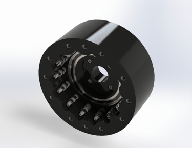
The housing also possesses heat set inserts at the top of it to allow for the attachment of a lid to close off the assembly. They also allow the drive to be attached to a testing rig for torque specing.
Low Speed Output Shaft:
This component outputs high torque at a reduced speed determined by the reduction ratio. It contains output pins that interact with the bearings in the discs to create the sought after reduction.
The DREAMMAKER output shaft is split into two components which are rigidly attached by 6 M2 shoulder bolts with a 3 mm shoulder diameter. These bolts also act as the output pins for torque transmission.
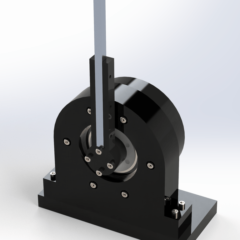
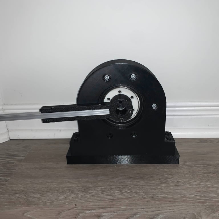
A 3D printed testing rig for efficiency analysis was also developed. It consists of a mounting bracket, which is attached to a base plate. A lever arm bracket is attached directly to the cycloidal drive's output shaft, and houses an aluminum 10mmx10mm aluminum extrusion that is 9" long.
The functionality of the assembly was validated before fabrication with the use of several SOLIDWORKS motion studies. The studies helped validate the eccentric motion and speed reduction of the actuator:
FINAL PRODUCT AND TESTING
The max reading on the scale I got during testing was roughly 3.6lbs, with a lever distance of about 0.816 ft. This means it outputted a max torque of approx 2.9376 lb·ft, which corresponds to 3.981 NM of torque. The stepper motor utilized possesses a rated torque of 0.59 NM. The actuator under perfect conditions should have a x13 torque amplification, so should output 7.67 NM of torque. Thus, the DREAMMAKER boasts an efficiency rating of roughly 52%. This could admittedly be better, but is decent for a 3D printed system.
While I was quite happy with the completed project, I found there were a few design choices and I wasn't a huge fan of in hindsight.
Changes I would make:
The motor mounts directly to the ring gear housing, and to take it out I have to disassemble the drive every time, making troubleshooting a pain. Future designs should utilize a shaft coupler instead for ease of access.
The design was much more expensive than I would have liked because I used very specific hardware. It could have been much more cost effective.
The design is a bit too bulky for my liking and could be made more compact.
The DFMA aspect of this project wasn't the best. The assembly was much more tedious than it should have been, and I honestly used more hardware in specific places than I needed to, shooting up costs and complicating manufacturing/assembly.
MORE DOCUMENTATION

