DRONE DESIGN CHALLENGE
For this design challenge,both the landing gear and ESC case had to meet a specific set of criteria. The requirements for the ESC case were as follows:
Must be able to be mounted to a 30mm x 30mm grid of M3 clearance holes.
Your case must be able to be 3D printed
There must be clearance for wires to be connected to the ESC terminals
There must be clearance for the capacitor installed on the ESC
The wire terminals should be protected on the top and bottom to prevent someone or something from accidentally contacting or shorting them.
There must be some form of ventilation to allow airflow to passively cool the ESC.
The requirements for the landing gear were as follows:
The total mass of the landing gear should be below 500g
The landing gear should be designed to break at the joint connecting it to the main frame if it has a hard crash, but not on a normal landing.(This is hard and we’re not looking for it to be perfect, just have an explanation in mind as to how your design meets this).
Your landing gear must be mounted to the main x-frame tubes, you may add mounting holes for this.
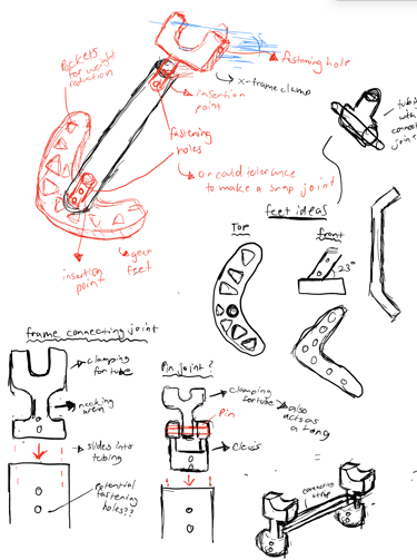
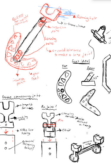
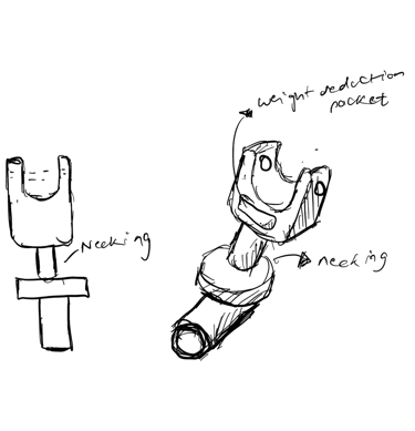
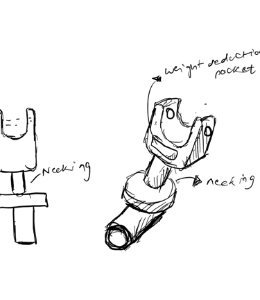
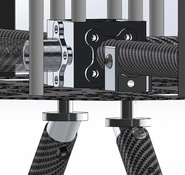
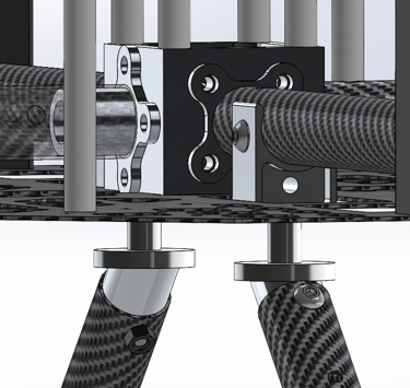
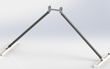
With this list of requirements at hand, I began to sketch out ideas and concepts. I spent time playing with case form factors and clamping methods for the ESC, as well as different ventilation designs. I also spent extra time thinking about a joint design that would be optimal for achieving the desired goals. My ideation and research led me to the idea of a "fuse" connection. A linkage in which there is a part with a considerably smaller cross sectional area, called the "necking" area. This decrease in cross-sectional area allows the necking area to yield first under high stress. I planned to make a joint where the necking area is responsible for connecting the tubing to the frame, in turn presenting a feasible solution to the set criteria. I also pondered material selection, and decided to use a mixture of 3D printed components and 6061-T6 aluminum to design the landing gear, utilizing pockets and lightening holes to ensure it met the weight requirements. I also decided on a general mounting angle of 45 degrees in reference to the horizontal as this generally provides a good mix of stability and flexion for shock absorption.
BACKGROUND
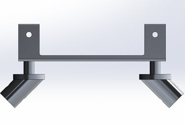
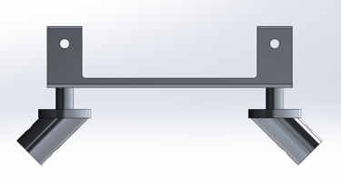
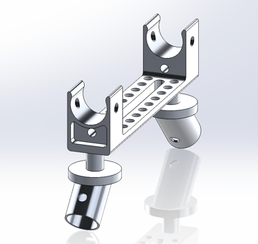
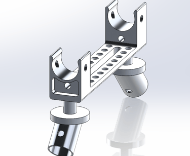
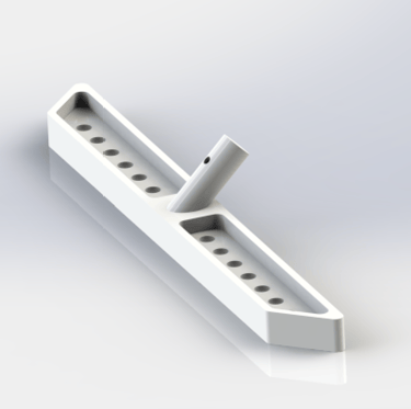
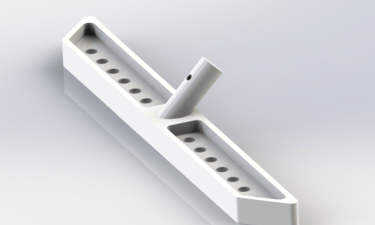
I then modeled the main connecting joint. The joint is made out of aluminum 6061-T6. It also features pockets and lightening holes for weight reduction. It implements "fuse" connection geometry, with the connection between the airframe mounting point and tubing connection being significantly smaller in area.
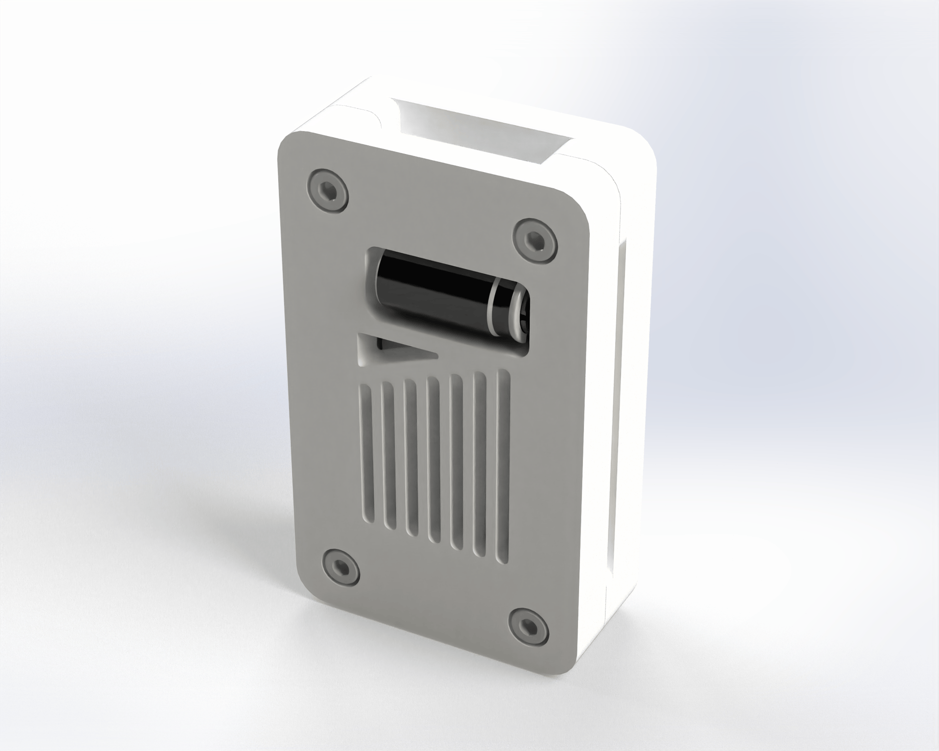
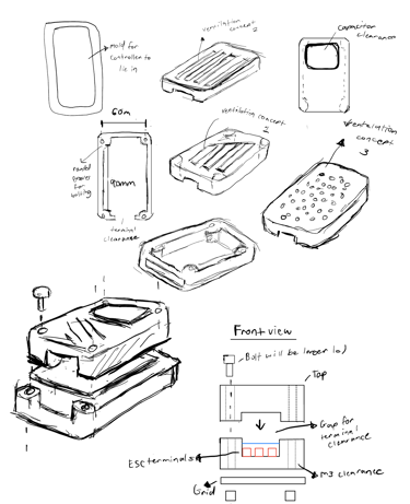
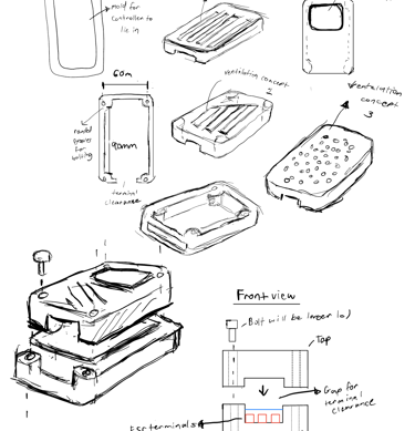
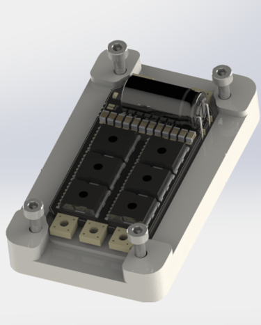
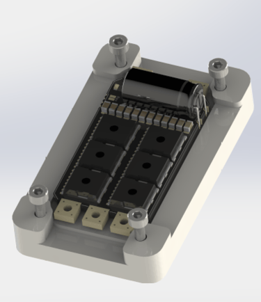
I first began by modeling the ESC case. I implemented a loose press fit on the bottom part of the case to help initially place the ESC when mounting. The top part of the enclosure was designed so that when attached to the bottom piece and bolted in, parts of its inner inner wall strategically mate with the ESC, clamping down on it and acting as a means of fixturing.
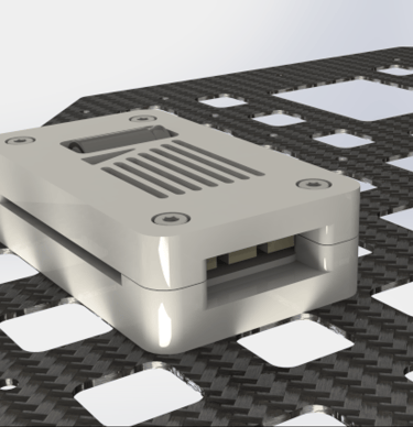
The case has an aesthetic form factor and has clearance for capacitor access and terminal access. The terminal pins are fully protected from both the top and the bottom, and both the bottom piece and top piece possess grills for ventilation. The design is also easily 3D printable, having lenient tolerances and possessing appropriate filet radii .
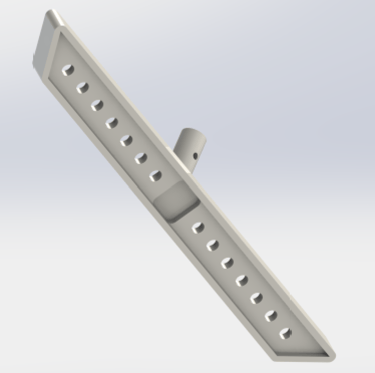
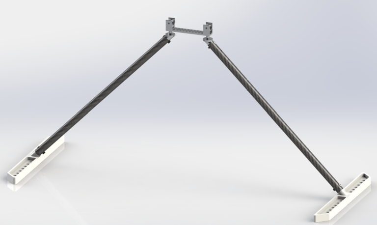
I then moved on to the landing gear. I started with designing the feet. The feet were designed to be 3D printed, featuring strategically placed pockets and holes to decrease mass while retaining enough structural integrity for landing. The foot has a mounting point that slides into the carbon fiber tubes, aligning with mounting holes for bolting.
The complete assembly weighs 491.6 grams, cutting it close, but ultimately meeting the set constraints.
DESIGN BREAKDOWN