THE SCOOT-E
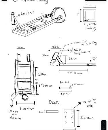
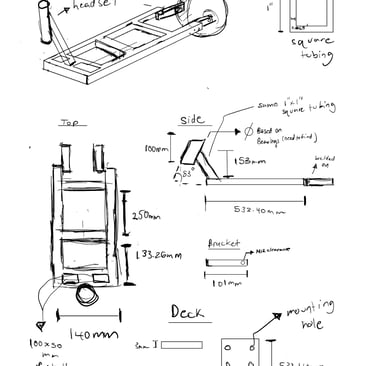
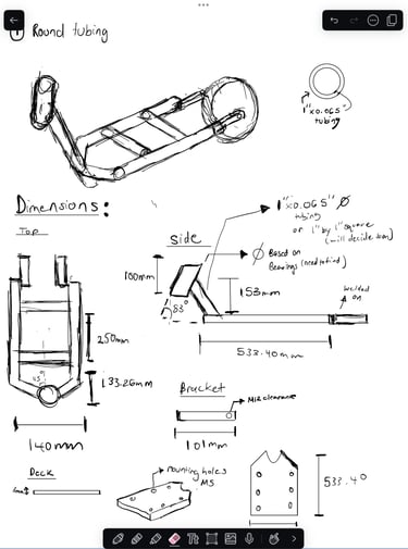
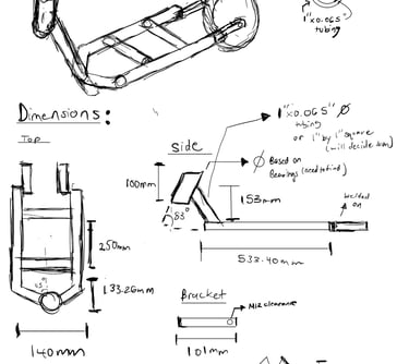
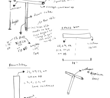
The Scoot-E aimed to resolve problems with last year's attempted vehicle, that being issues with weight and manufacturing. The team began with base ideation and product sketches. We broke down key subsystems and ideas for the structural design of the build. The pictures to the left showcase some of the sketches I produced during this phase. I wanted to produce a lightweight but structurally effective frame that also had an aesthetic form factor.
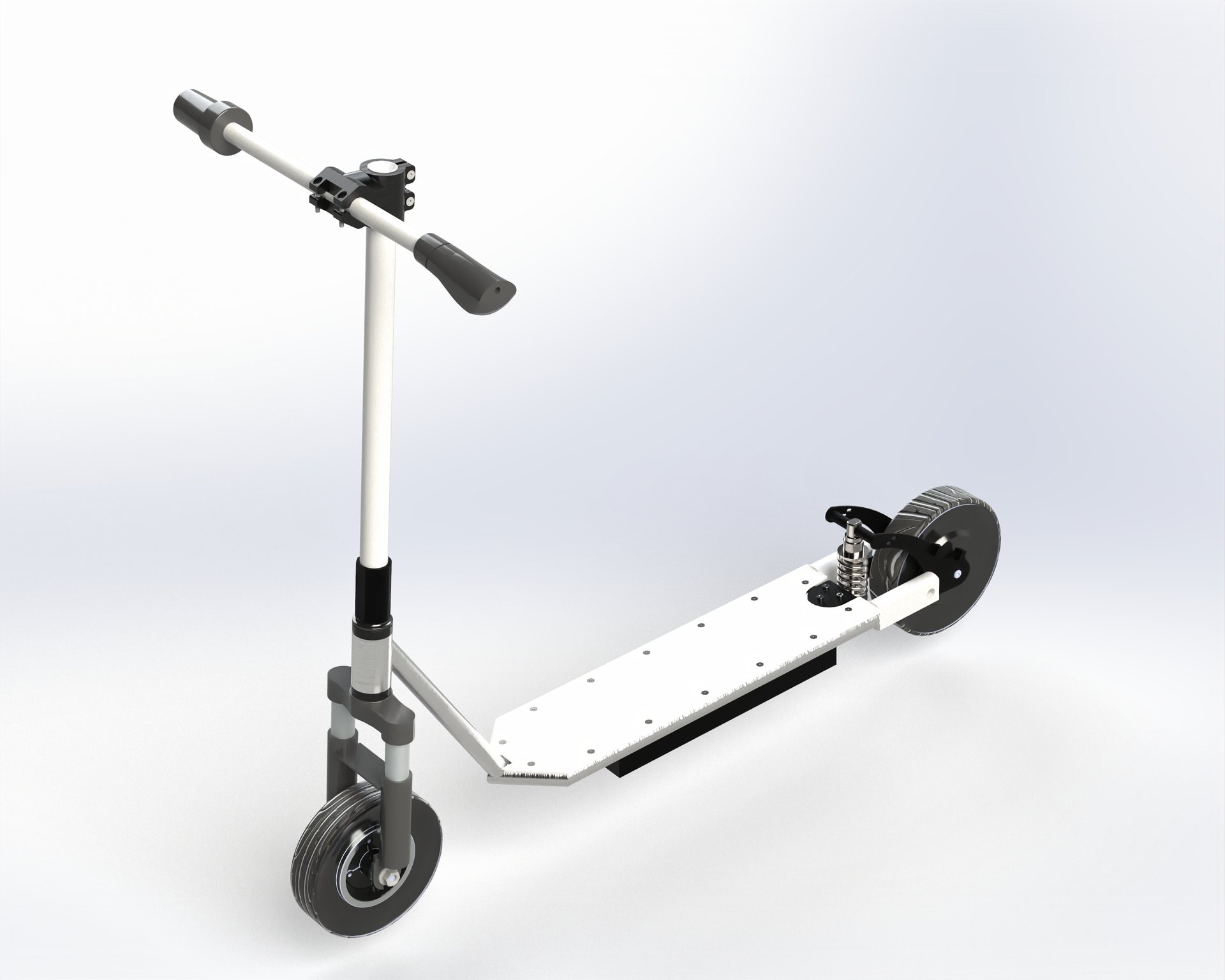
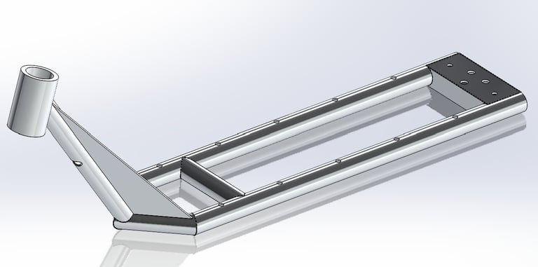
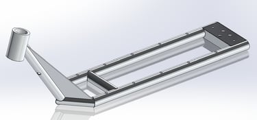
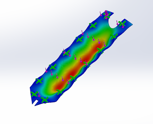
After deciding on a final design we moved into developing CAD for FEA to ensure safety, as well as to get an idea of how the build would be assembled . I was responsible for the design and modeling of the frame, steering system, deck, and steering clamp. I was key in producing the CAD assembly of the complete build. I also assisted with FEA and used it to validate the strength of the frame and parts such as the deck and battery box.
BACKGROUND
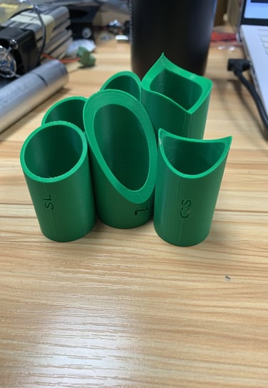
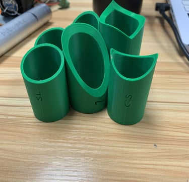
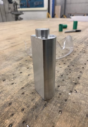
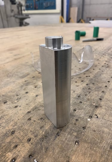
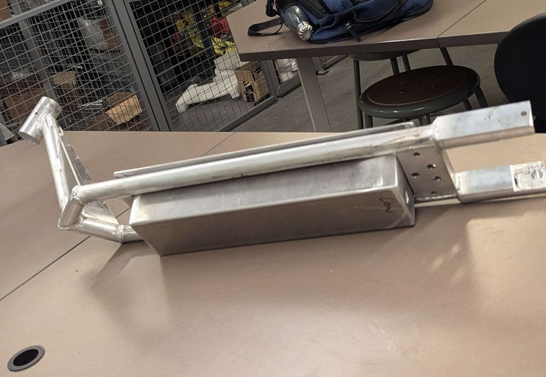
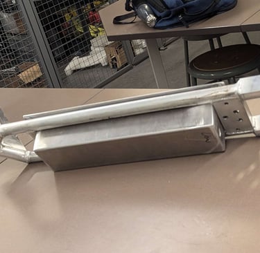
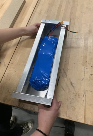
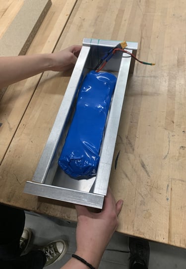
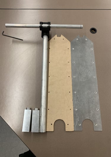
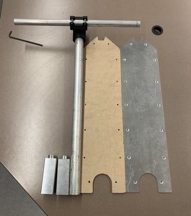
I also prototyped the clamp for the handle bar assembly to test tolerances and fits. I started the production of the vehicle's rear wheel mounting brackets by machining key features from round aluminum 6061-T6 stock using a mill and a lathe. I also notched much of the tubing using an angle grinder. I created 3D printed tube notching guides (The green prints in the photos) with some SOLIDWORKS wizardry that I used to mark the tubing for notching. I also cut and bent the sheet metal that was welded together to form the battery box.
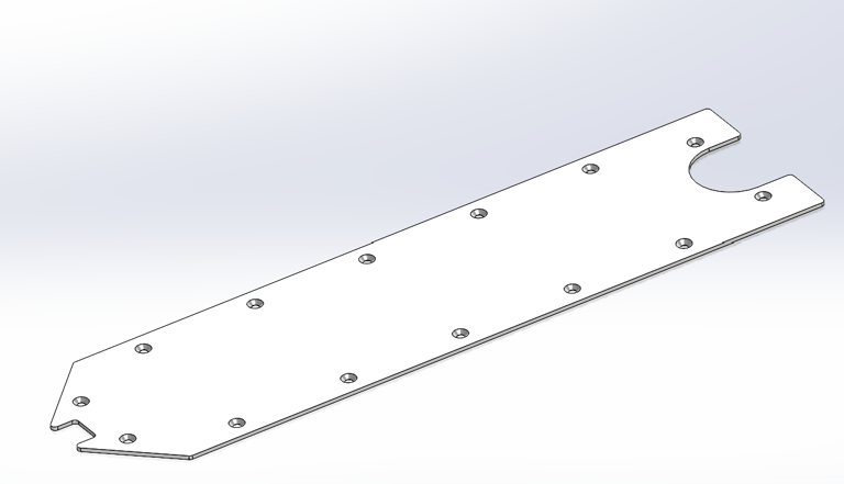
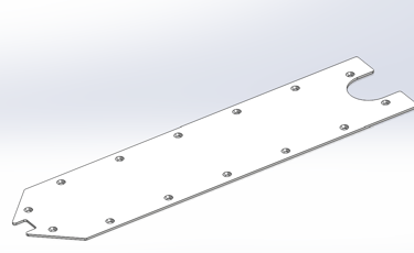
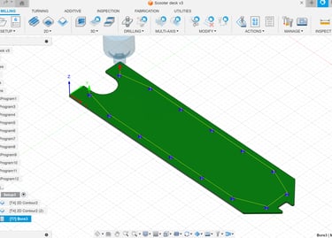
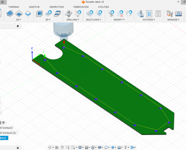
I had access to a CNC mill at work and designed the deck to be easily milled. I opted for 3mm thick 5000 series aluminum as the material for the deck. I also validated the strength of the deck with FEA to ensure minimal deformation under load. The deck contains clearance holes for mounting to the frame. They are countersunk to prevent any bolt heads from sticking through the frame. I transferred the SOLIDWORKS file over to Fusion 360, and used Fusion 360 CAM to generate toolpaths and G-code for the job.
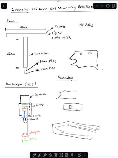
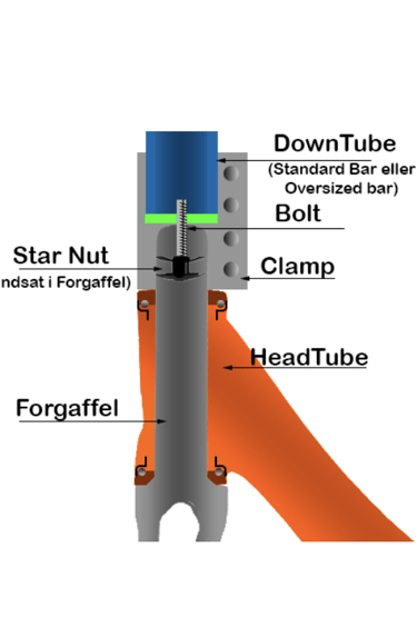
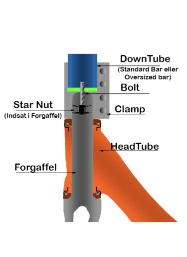
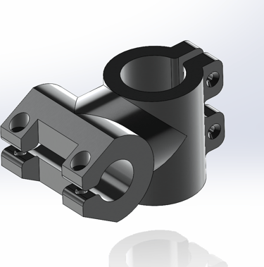
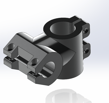
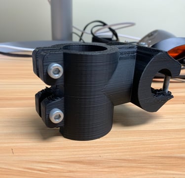
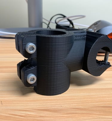
The clamp and steering system were also designed by me. The clamp was designed for attachment of the handlebar to the scooter stem, as welding wasn't an option due to the small outer diameter of the handlebar as compared to that of the stem. The clamp was designed to farbricated out of 6061-T6 aluminum using CNC machining . The steering system was designed to mimic that of an SCS compression. It utilizes a threadless headset press-fit assembly, with press-fit bearing cups, aluminum bearings, and a shim to adapt diameters. A star nut is used to secure each component in place and pull everything together, and clamp is used to secure the stem on the assembly and prevent wobble.
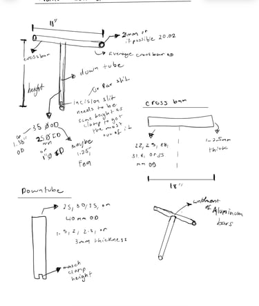
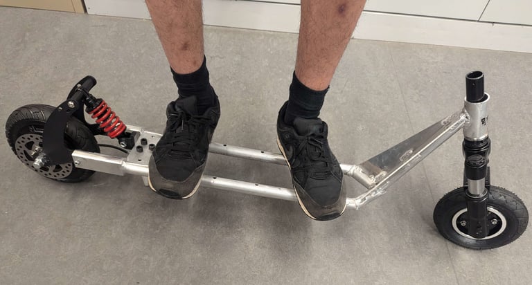
I designed the frame with a triangular like base shape to save on material while retaining structural integrity. The frame was also designed with DFMA principles in mind. Round tubing was selected as its geometry allows for more even force distribution, thus making a stronger frame. The frame was also designed with simple angles allowing for relatively easy notching during the manufacturing process. The material selected for the frame was 6061-T6 aluminum, as it serves as a lightweight and strong option for the needs of the project. This would yield a significant weight decrease (about 8%) as compared to the previous year's scooter which was manufactured out of steel.

DESIGN BREAKDOWN
THE DRAMATIC ENDING
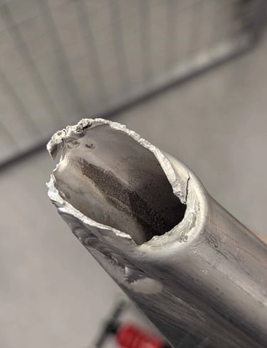
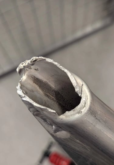
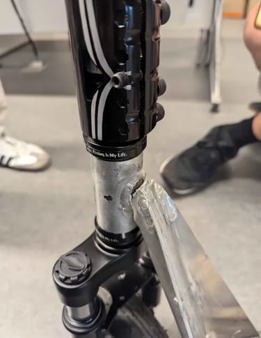
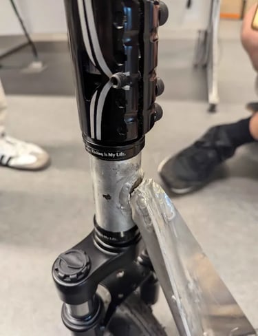
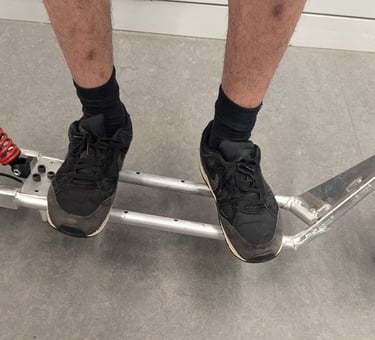
Ultimately, the Scoot-E did not have the dream ending that was envisioned. The scooter was fully assembled, and testing was ready to begin. But upon testing, the headtube failed and there was bending of 5 degrees near the front of the frame. Ultimately, all the hard work we put in led to failure.
All in all, the Scoot-E holds a special place in my heart, as it was my first major personal project. Despite the failure, I learned a lot about design, FEA and failure analysis (ALOT!), and how to lead a team so failures like the one that occured don't happen. I am a man who likes to reflect on how I can be better and this is a failure I will never forget.