PHANTOM QDD
The phantom QDD is a 3D-printed quasi direct drive actuator I designed for compliant, efficient, reliable, and cheap robotic systems. I undertook this project due to my growing interest in dynamic robotics (quadrupeds, bipeds, etc) and love for comprehensive research and design. Phantom QDD presents an affordable and accessible approach to high performance actuator development. This page is a summarized presentation of the development process. For a deeper dive into the technical aspects behind certain decisions, the report attached to the bottom of this page can be read.


SUMMARY
Specs:
Peak Holding Torque: 17.61 NM
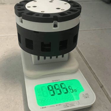
Weight: 2.1 lbs (955.5 g)
Efficiency: 78%
Reduction: Planetary (9:1)
Controller: Makerbase XDrive MINI ( AS5047P on board)
Cost: $236.06
Max Speed: 1788 RPM
Passive cooling
Background
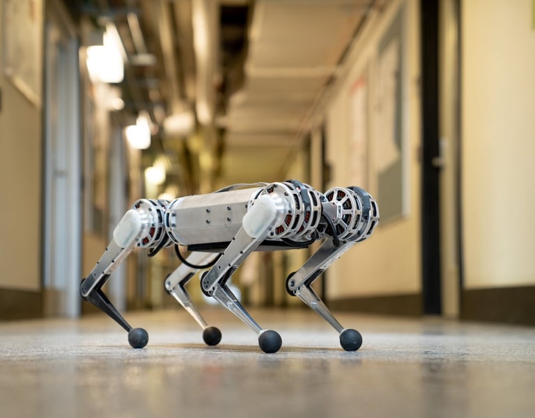
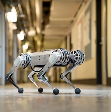
Quasi direct drive actuators were first heavily popularized by the M.I.T mini cheetah and are a staple in hobbyist quadrupedal robotics. They consist of a radial BLDC motor with high torque density coupled with a low reduction gear drive (usually between 3:1 and 10:1, though this isn’t necessarily a hard set rule.). This setup allows said actuators to achieve high levels of output torque and general performance while behaving as a direct drive system, in turn improving compliance, backdrivability and efficiency as compared to traditional designs.
DESIGN BREAKDOWN
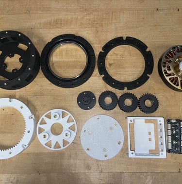
The phantom QDD development cycle consisted of two major phases. The first phase focused on generating a proof of concept for the quasi direct drive scheme. This involved creating the first prototype known as phantom v1. This version was a very rough draft, developed with the purpose of testing out design features and validating actuator performance. It consists of a few major components:
Eaglpower LA8308 90KV Brushless Motor:
This powerful and compact motor drives the actuator. It’s torque density is large and it is capable of reaching very high RPM.
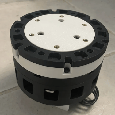
Motor Housing:
This housing rigidly attaches the motor to the actuator. It contains vents for passive cooling to ensure the motor is able to dissipate heat under max operational conditions. Pockets were also added to reduce the overall weight of the actuator.
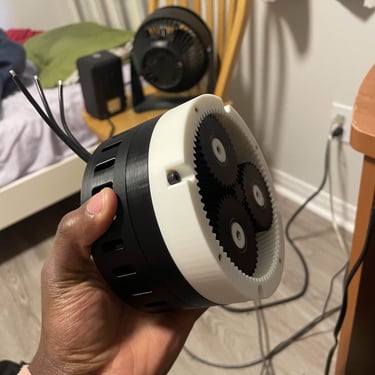
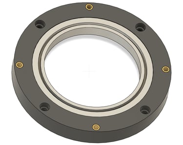
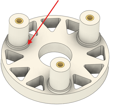
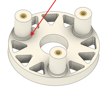
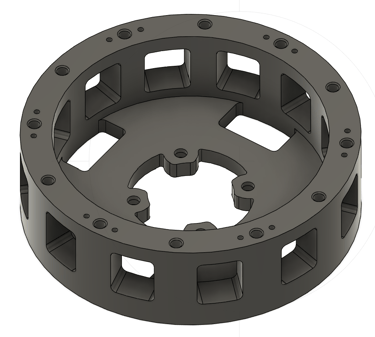
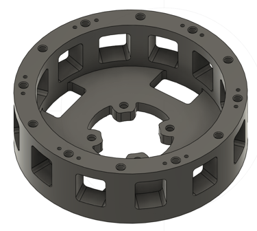
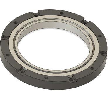
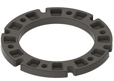
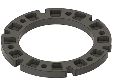
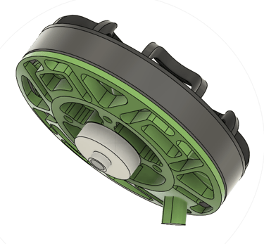
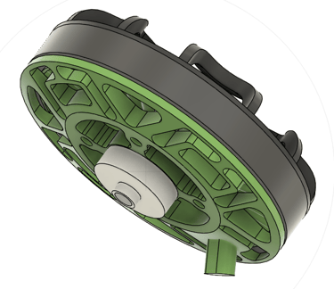
The carrier housing holds the gear train in place. This design places the output hub inside of the carrier housing, allowing the actuator to operate without a cover.
Carrier Housing:
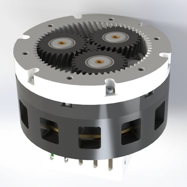
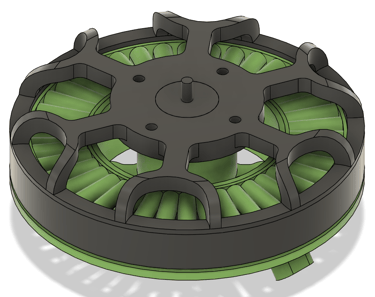
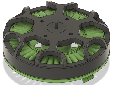
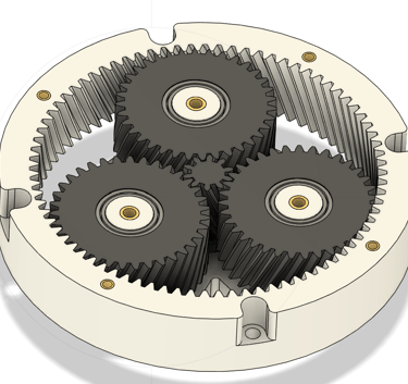
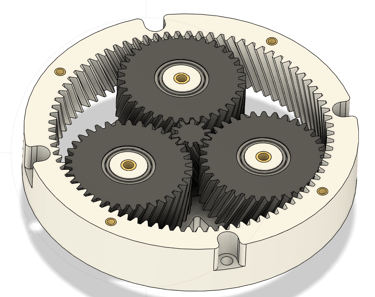
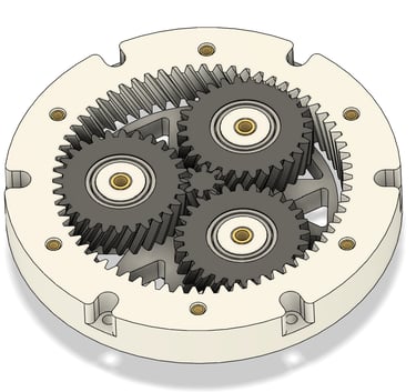
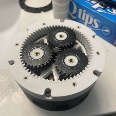
Gear Train:
Phantom utilizes a planetary gear train optimized for peak performance. It consists of helical gears, which provide superior levels of load resistance and efficiency as compared to spur gears. They are also quieter than spur gears and are more resistant to wear. The helical gear angles were optimized to minimize helical thrust while maximizing the intrinsic benefits associated with the gearing. Furthermore, the gear height, module, and number of teeth, were optimized to minimize size while retaining strong performance and longevity. Each of the planet gears are equipped with press fit bearings to circumvent frictional losses and provide smooth rotation. The planet carrier also has nubs for the planet gears to rest on which help to minimize plastic to plastic contact between the rotating components, in turn reducing friction.
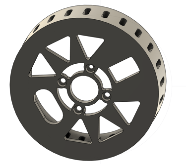
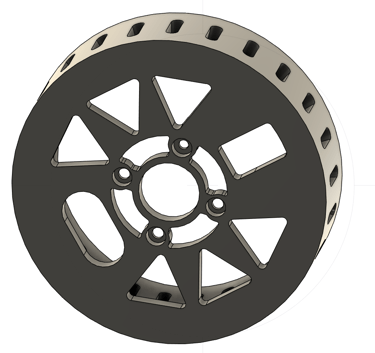
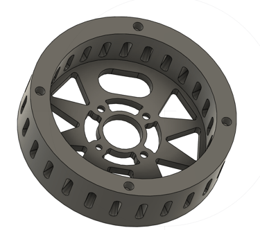
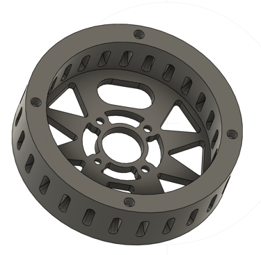
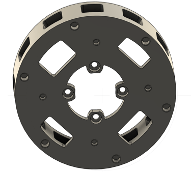
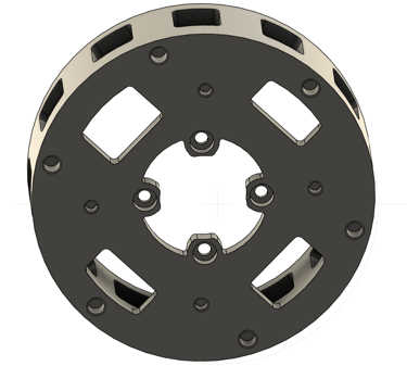
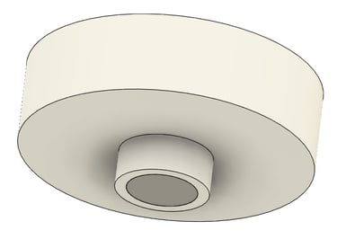
The Output Hub:
The output hub expresses the amplified torque from the gear train. It is connected to the gear train with the use of 3 M4 bolts, establishing a rigid connection that ensures stability and precise alignment.
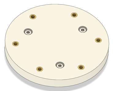
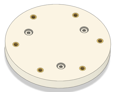
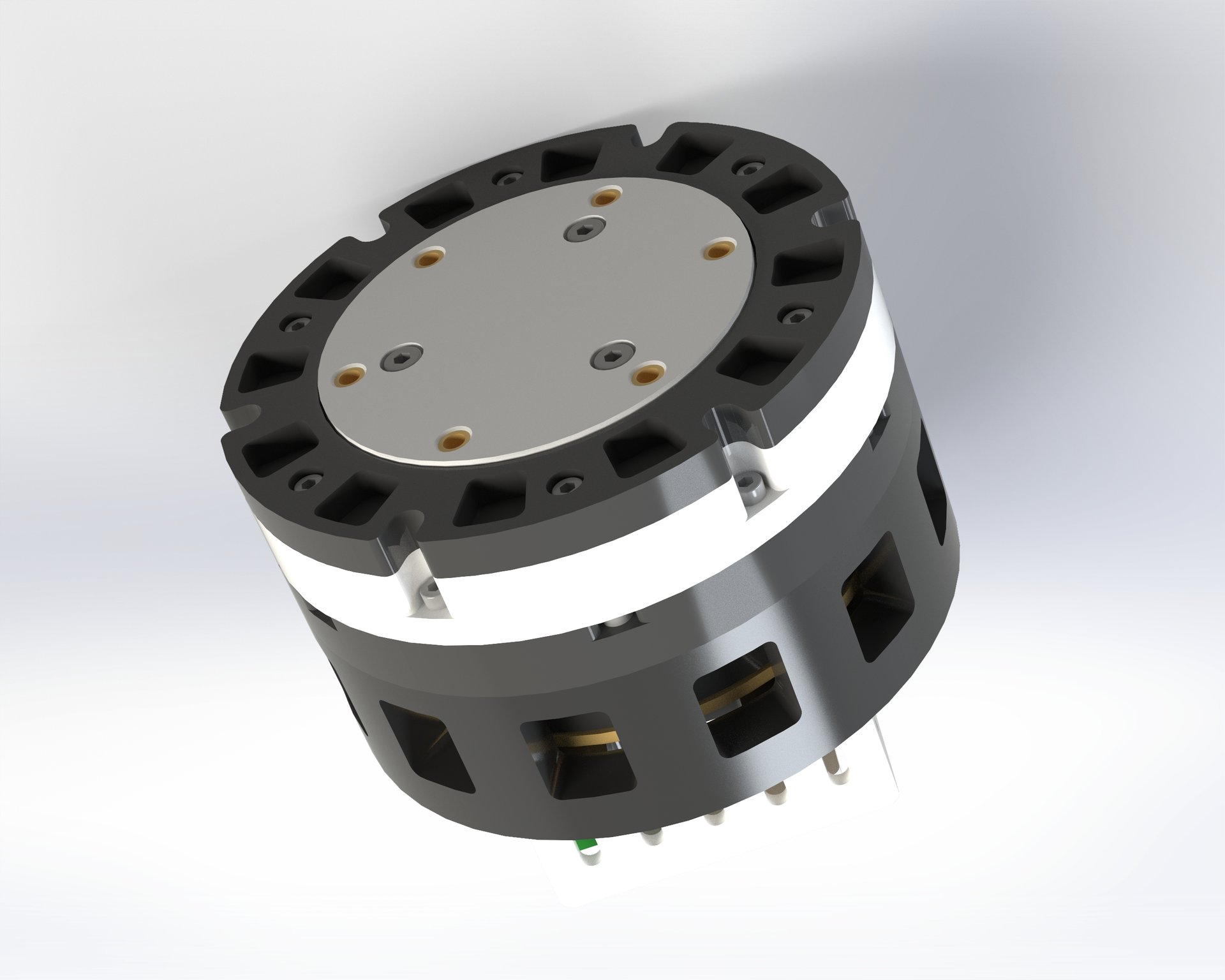
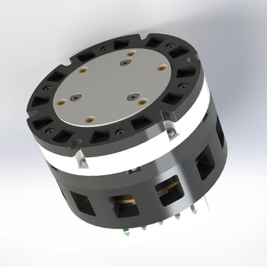
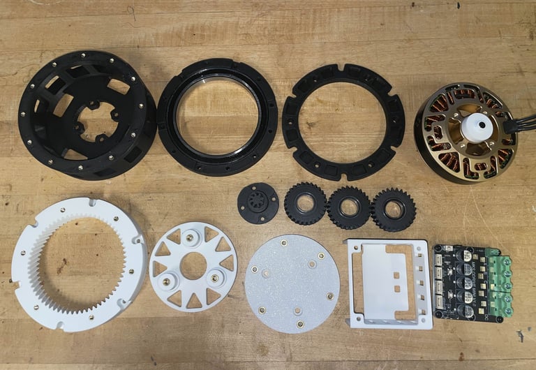
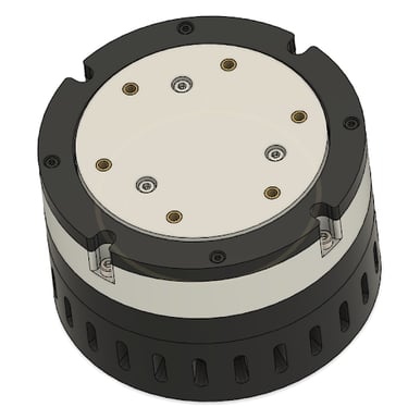
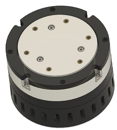
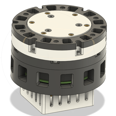
All these components come together to form the final assembly:
FABRICATION AND TESTING (V1)
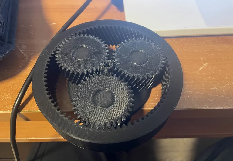
After completing the CAD model and doing a design review, I started manufacturing the build. Firstly, I printed a gear train prototype to determine appropriate clearances and to see if the reduction was actually accurate. This is where I ran into the first problem during the Phantom’s development. Initial prints were prone to excessive binding and the motion was quite choppy. Some couldn’t even be driven at all. Assembly was also difficult, as fitting all three planet gears into the ring gear required excessive amounts of force.
One of the first gear train prototypes
I was able to eventually solve these issues through trial and error. I adjusted the clearance of the gears in Fusion 360 using a helical gear generator and printed several more prototypes to eventually land on a design that minimized backlash, eliminated binding, and allowed for ease of assembly. After this validation cycle, I then went on to 3D print the remaining components and assembled v1 of the Phantom for testing. After assembling the actuator, I was glad to find that it was easily backdrivable, which was one of the most important constraints for the design.
Backdrivability showcase
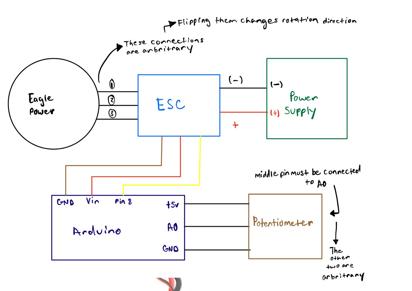
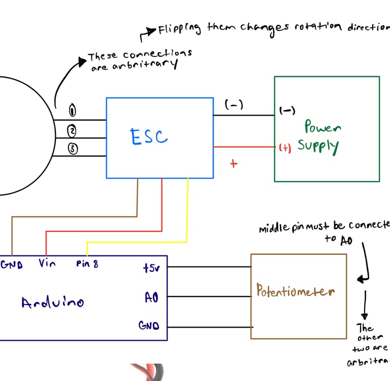
To test v1, I used a simple wiring setup that allowed me to control the brushless motor using an Arduino via PWM signals. There were quite a few limitations with this approach. The motor was controlled with a potentiometer, but was not able to hold a specified position. There was also no means of torque control, meaning the only way to maximize output torque was by applying physical resistance to the motor. At this point in the process, however, position control was not needed, as the goal was to verify basic functionality and performance. After validating the actuator was able to move and that the reduction was working, I went on to do load testing. Since I couldn’t hold a specific position due to my limited setup, to get an idea of how strong the prototype was, I attached a lever arm to the output hub and used it to lift objects of varying mass. Testing footage, photos and wiring diagrams for V1 are shown below:
With a lever arm of approximately 0.130m in length, the actuator was able to lift about 32 lbs (142.34N), meaning it was able to express about 18.5NM of peak torque. This prototype weighed in at 992.5 g, which is about 2.2 lbs.
In terms of performance, I was pretty happy with this first prototype, but I realized there were a lot of improvements that could be made to the design. Firstly, it was too big. I knew it could be significantly more compact and that I could shave off some more weight through optimizing the geometry of the design. Secondly, I now needed to integrate a micro-controller and encoder into the design to allow for torque and position control. Lastly, there were certain areas in the design in which I could have better minimized losses caused by friction in between components. With this checklist in mind I started my design of V2, which would end up being the final prototype.
RE-DESIGN BREAKDOWN (PHANTOM V2)
Compactness and Weight Reduction
The first major point of re-design focused on improving compactness. To do this, I decided to reduce the size of the gear train, in turn allowing me to reduce the size of the additional housings. Initially, I did not use the minimal amount of teeth possible to achieve my desired gear reduction because I wanted to minimize undercutting, the phenomenon in which gear teeth are weakened because they fall below a certain number. I later decided however that for the sake of compactness, I was willing to introduce this risk, as only the sun gear would have a small enough amount of teeth for this to be a potential issue. Additionally, other reliable designs I found online also possessed sun gears that were below the recommended threshold for undercutting avoidance, yet did not encounter any major performance issues or failures during testing.
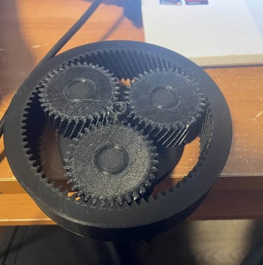
Initially, the planet and sun gears were 20mm thick, with the ring gear being 22mm thick. This choice stemmed from the fact that I wanted to ensure the 3D printed gear teeth would be strong enough to not heavily deform and wear during use. After looking into other 3D printed designs, I found out that this decision was a bit overkill, and I would be able to get away with significantly thinner gears. I reduced the thickness of the sun and planet gears down to 10mm, and the thickness of the ring gear down to 15mm. Finally, I changed the settings I printed the gears with. Originally, I was using 75% infill with 4 wall loops to print my gears, which was definitely overkill and added unnecessary weight. Instead, this time I opted to use 50% infill for each of the gears, retaining the 4 wall loops, and utilizing a gyroidal infill pattern for strength in all directions.Like with version 1, I 3D printed a prototype to validate if the reduction mechanism was functioning properly, and in this case to test if any notable effects of undercutting could be observed.

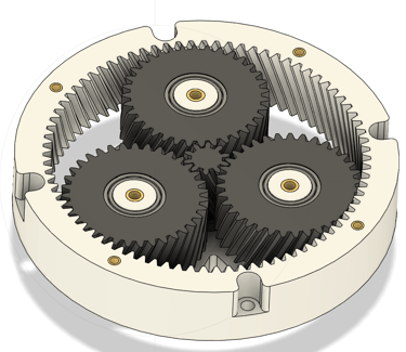
Old Version (V1)
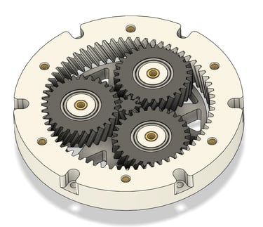
New Version (V2)
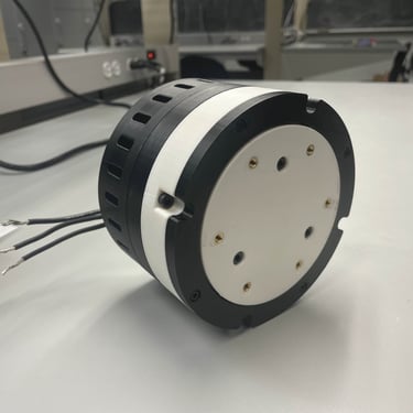
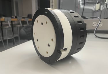
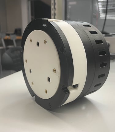
After finalizing the gear train re-design, I went on to modify the motor and carrier housings. Firstly, I significantly reduced the diameter of both from 130mm to 118mm. I also reduced the height of both housings as well. I reworked the motor housing’s ventilation pattern and added holes for heat set inserts to allow the actuator to be mounted to different objects. The heat set inserts are also used to mount a micro-controller housing to the actuator as well.
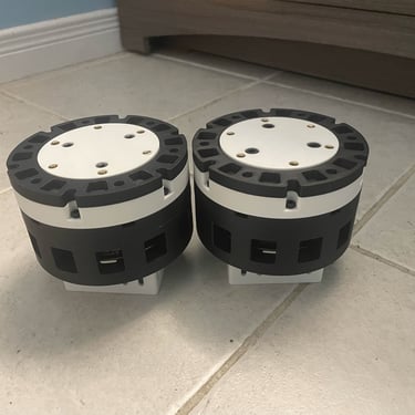
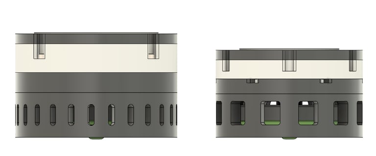
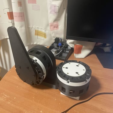
The photo below shows a comparison between the main bodies of version 1 and version 2 to really highlight the improvements in compactness:
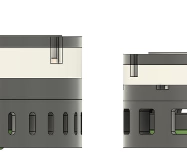
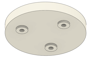
Lastly, I re-designed the actuator cover, adding pockets because they looked cool and also helped remove some unnecessary weight.
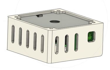
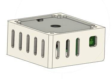
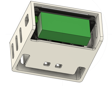
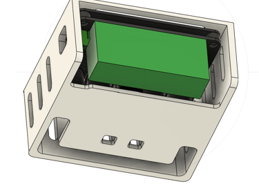
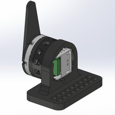
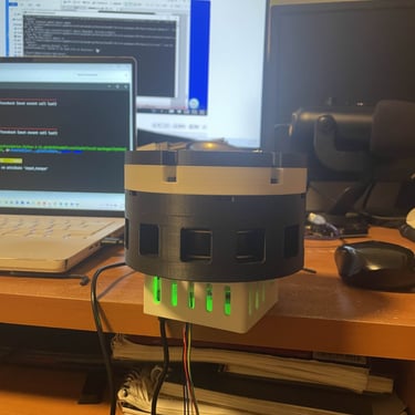
Motor Controller Integration
To integrate the motor controller a encoder magnet is required. I designed a magnet holder that attaches directly to the motor shaft, allowing the magnet to rotate with the shaft, in turn allowing the onboard Xdrive mini encoder to work out the motor’s position. Additionally, I designed a housing that attaches to the actuator’s base. It includes ventilation for passive cooling and ensures access to all key connection terminals for wiring.
Friction Reduction
To reduce friction between rotating plastic components, I added nubs to the bottom of the output hub. This way, frictional buildup between the planet gears and the output hub during rotation is minimized.
After making these changes, V2 was complete. I am quite happy with this design, specifically how much more compact it is. I also think it is much more aesthetically pleasing. Version 2 weighs in at 955.5g, a decent reduction from the initial 995.5g for version 1.
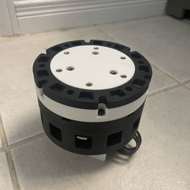
TESTING AND RESULTS (PHANTOM V2)
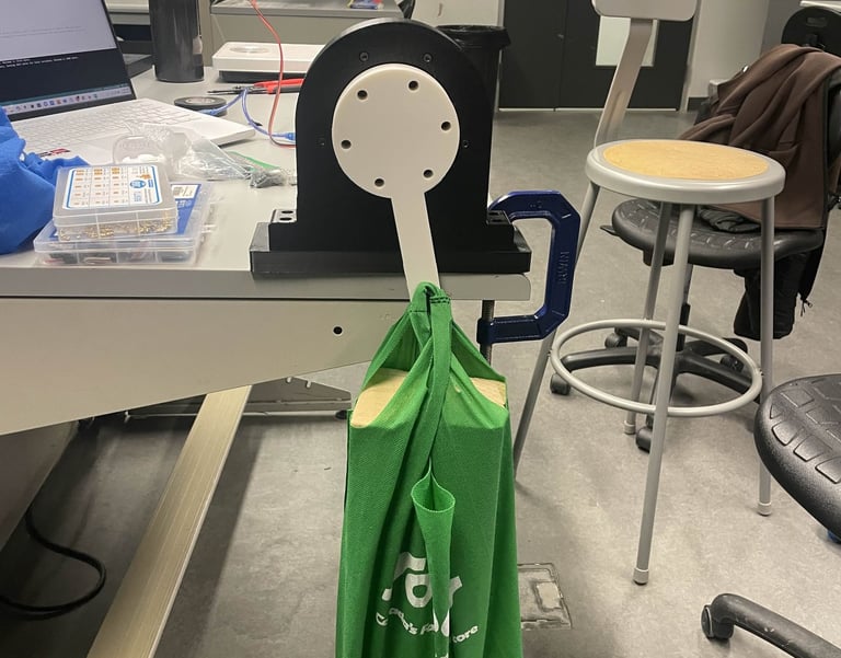
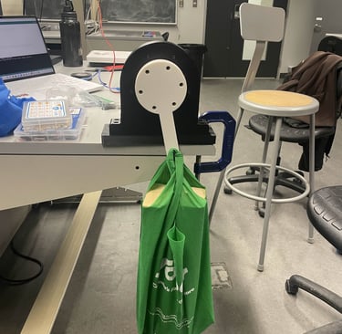
I did a lot of testing to determine the presented actuator specifications. I firstly started by calibrating my motor using the Odrive control tool and python. After getting position control working, I went on to plan out my torque testing. I first designed a stand for the actuator that I used to secure it during testing. I also designed a lever arm that attaches to the actuator and is used to press down on a scale. Using the scale reading and the lever arm length, I was able to calculate the max holding torque.
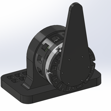
After running a few test cycles, the largest reading on the scale came out to 24lbs, which translates to 106.76 N. This was achieved with a lever arm of 0.165 m, meaning there was a torque output of 17.61 NM. I then went on to vibe code a script to test the actuator’s velocity control. I was able to toggle the actuator between different rotational speeds. Testing the max speed yielded a result of 29.8 rotations/ second, which corresponds to 1788 RPM. The backdrivability of the design also remained intact, and in torque control mode, the actuator was able to loosen and stiffen like a virtual spring. Below are several clips and photos from the fabrication and testing process:


FUTURE IMPROVEMENTS
While I am quite satisfied with the design and its performance, there is one flaw that I still hope to fix. The output hub is prone to wobble at higher speeds. Additionally, when cover-less, the gear train occasionally pops out when operating at large RPMs. The popup was quite unexpected, as while version 1 did also have the presence of small amounts of wobble, issues with popup never occurred. I theorize that the popup occurs due to a mixture of reasons. Firstly, I believe that the fit between the planet carrier and bearing is a bit too loose and as a result it has a tendency to pop out under accelerations at higher speeds. Additionally, I also think the helical thrust generated by the gear train is exacerbating this problem.
I made a few attempts at fixing this. Firstly, I scrapped the nub re-design on my output hub and returned to the original version to increase the amount of surface area that clamps down on the planet gears. I also swapped the hardware that connects the output hub to the planet carrier from M4s to M5s to hopefully increase clamping force. This didn’t work however and the wobble and pop up still occurred occasionally at high RPMs. In the future, I think the easiest solution is to add an additional bearing to the output hub in which a shaft on the sun gear would fit through. This should significantly increase the bracing and help minimize wobble. I'm also considering lowering the helix angles of my gears to further reduce axial thrust, which should help with the pop-out issue.