PROJECT PANDA
SUMMARY
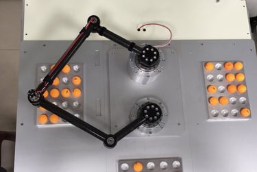
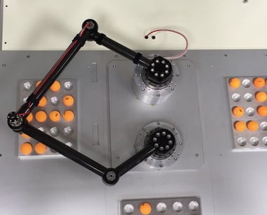
Project Panda is a compliant, precise, and fast 5R Parallel manipulator designed to be driven by two Phantom QDDs and controlled with inverse kinematics. I designed it to serve as a cheap and efficient means of completing useful and fun tasks such as organizing objects or drawing cool shapes. In general, I also just think 5R parallel robots are really cool.
Background
A 5R parallel robot is a type of manipulator made up of five rotational joints, where "R" stands for revolute and "5" means there are five such joints in the kinematic chain. In very simple terms, it is basically a 5 bar linkage driven by two motors. They are especially useful for planar pick-and-place tasks, as well as general robotics research and experimentation.
DESIGN BREAKDOWN
Mechanical Design
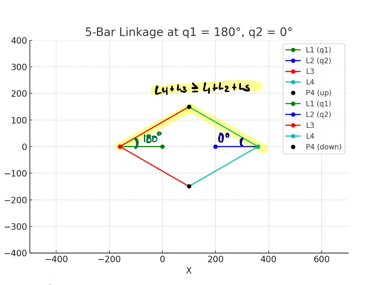
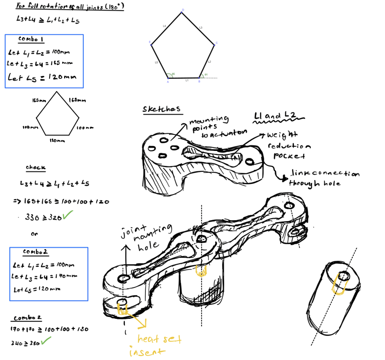
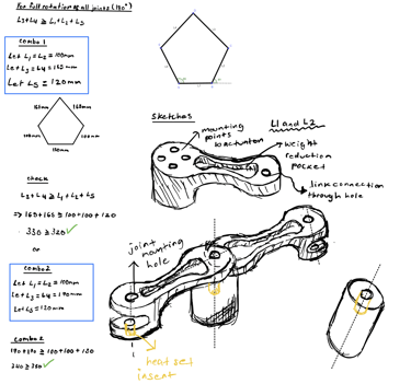
To design a valid 5 bar linkage, the following rule must be adhered to: L3+L4 > L1+L2+L5, where L represents the distance between each revolute joint.
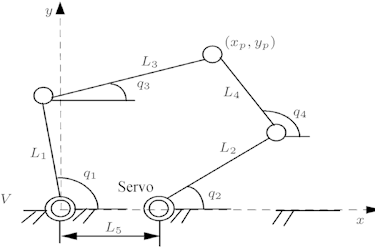
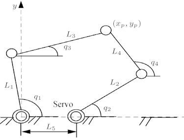
This is derived from the fact that when L1 and L2 are completely parallel with the linkage base, for the system to remain connected, the total combined length of L3 and L4 has to be equal to or larger than that of the total distance between the revolute joints of L1 and L2. If this restriction is met, then the linkage will be able to move through any other joint angle configuration without any issues. The diagram below gives a visual idea of this constraint:
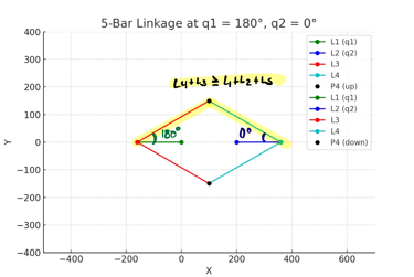
* Here you can see that if L4 and L3 did not meet the given restriction, this shape couldn’t be formed (note: L5 is the distance between the endpoints of L1 and L2)
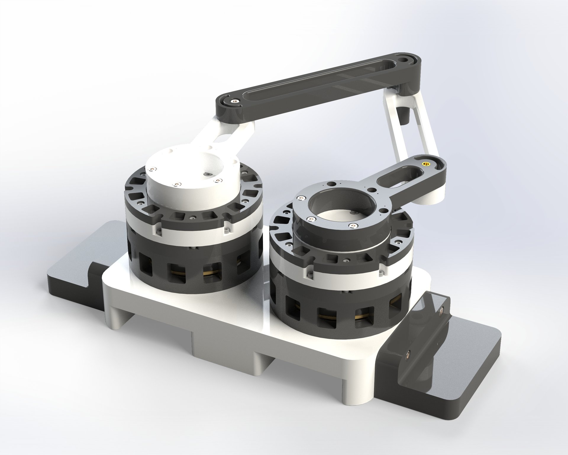
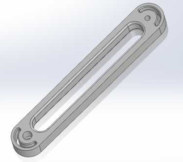
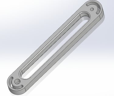
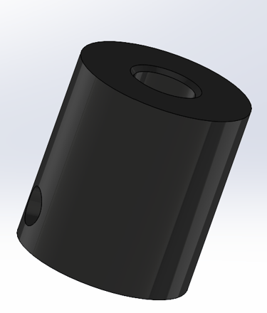
After getting an understanding of the geometry and its requirements, I started designing my linkages. To minimize the robot’s inertia, I aimed to make each link as light as possible without completely comprising structural integrity. The manipulator will not hold any significant amount of weight on its end effector, but I still wanted decently rigid links to allow the robot to be used in other domains, such as that of a quadruped leg, if I so choose to do so in the future. The end effector is also detachable and swappable, allowing for many different use cases.
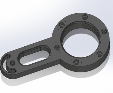
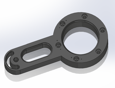
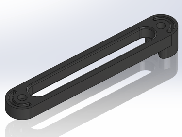
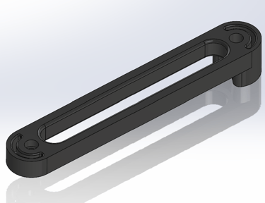
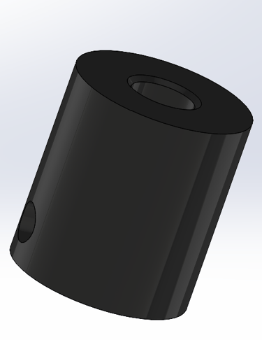
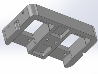
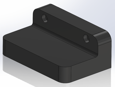
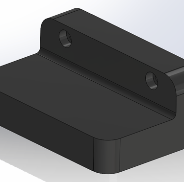
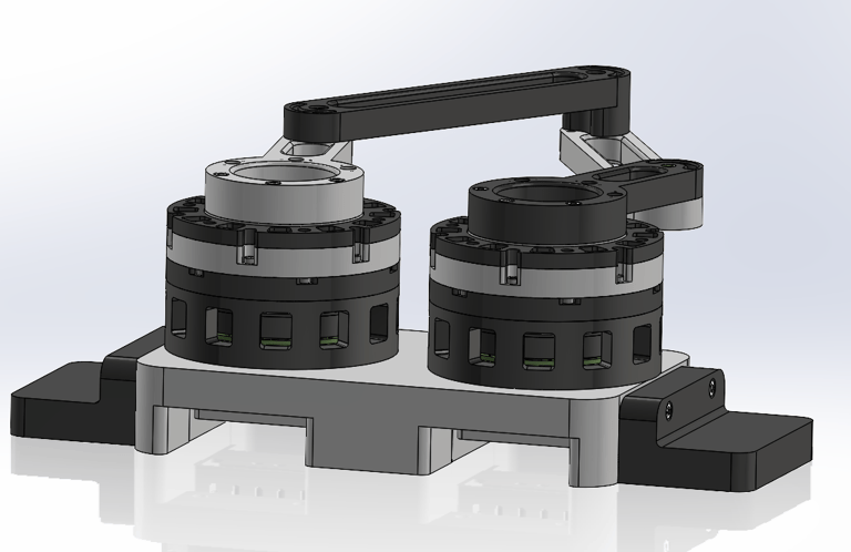
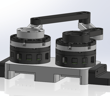
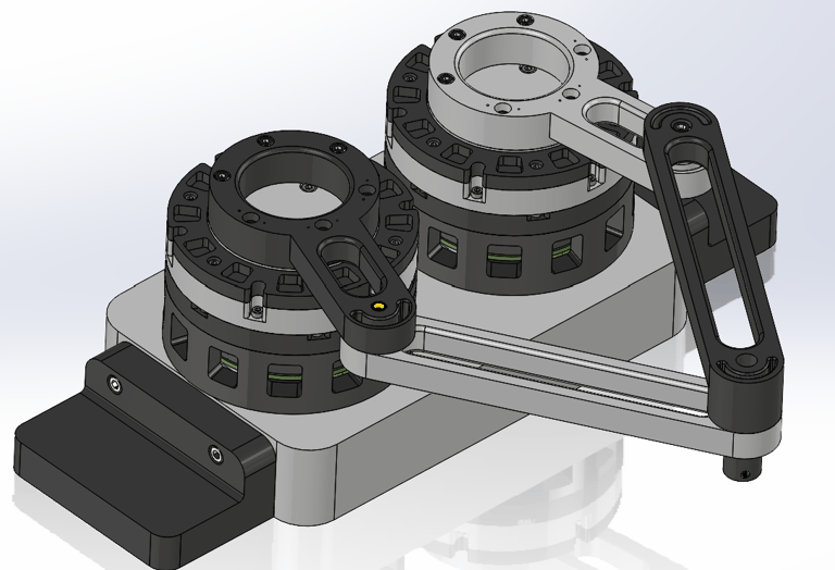
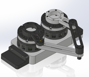
The driving actuators are attached to a base designed to allow for easy wire routing, with additional brackets attached to each side to act as points that can be clamped to a table during testing.
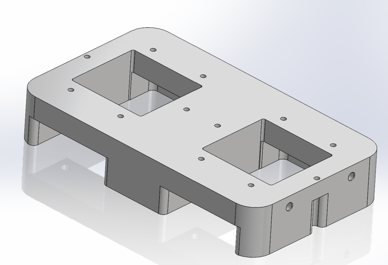
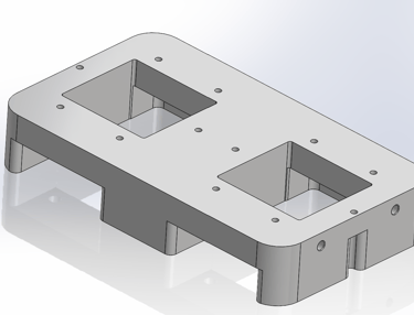
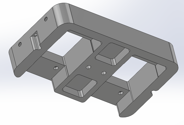
Together these components form the complete assembly:
Electrical and Software
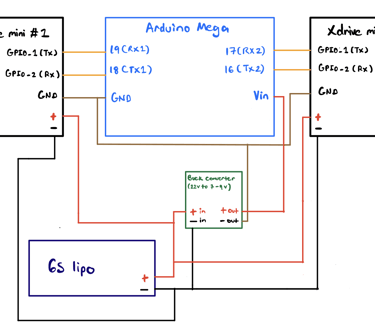
To control the robot, I plan to use an Arduino Mega to communicate with my actuators through UART/Serial connection. The robot will be powered by a 6S lipo battery, with a buck converter thrown into the circuit to ensure the Arduino does not get fried:
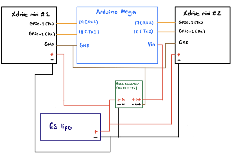
The Arduino will run an inverse kinematics solver to convert the desired end effector position into joint angles to send to the actuators.
Next Steps
Print components and manufacture the first prototype
Work out the inverse kinematic equations
Start testing and troubleshooting